CASE STUDY
MALADJUSTED GEAR ON THE "Elin type S" TAP CHANGER
The analysis of tap changer motor current showed to be a powerful diagnostic tool to detect mechanical binding, motor control malfunctions, as well as irregular operation around neutral where reversal switch operates.
This particular case was detected by comparing the position of the transition ripple on the DVtest graph with the motor current trace. It was recorded during our workshop at Minel repair shop in Barajevo, Serbia. This type of tap changer consists of a diverter switch and a selector.
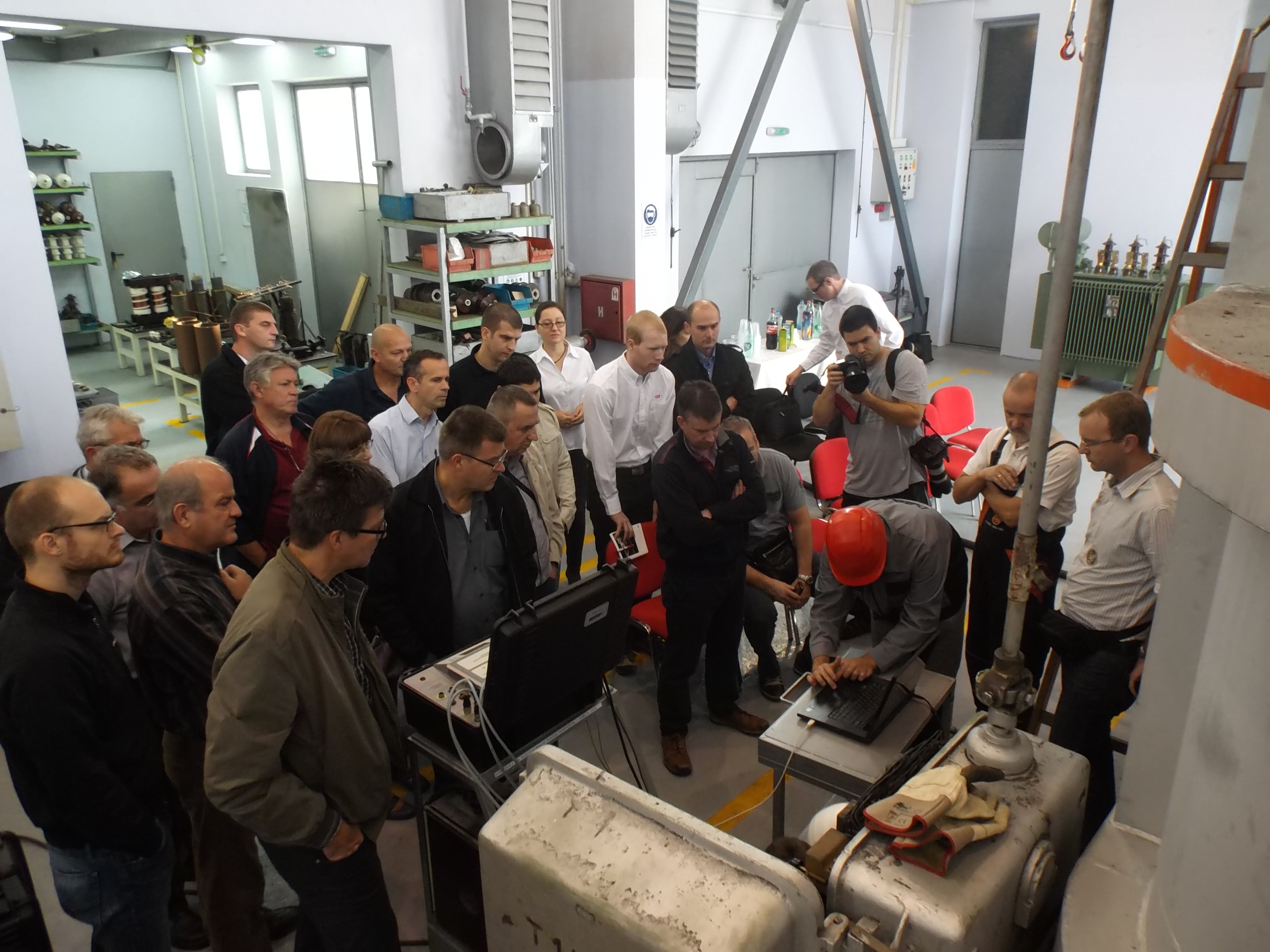 Participants at the workshop review the test procedure.
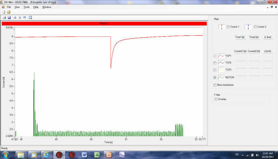
Here is the DVtest graph below, showing the motor trace in green and the tap changer operation in red. One can see that the position of transitions is not at the right place. As the motor charges the spring and the spring releases its energy into diverter switch operation - it should be close to the end of the motor operation, not at the beginning, like on this graph.

In order to further check the operation of the tap changer and find out the reason for such a strange behavior we performed measurement in the opposing direction. The graph below shows that the ripple is not at the right position either.
The video below shows the incorrect operation of this tap changer. Fortunately, at this repair shop the side manhole door on the tank was opened for selector switch verification. A diverter noise [bang] occurs immediately after the motor and motion of the selector moving contacts starts, and the motion ends at the wrong position.
It was decided to correct the mechanical gear operation on the top of the transformer. The mechanic opened the gear box and moved the gear by one tooth. This seems to correct the situation. We have repeated the measurement now that the gear is adjusted and obtained a completely correct position of the ripple as compared with the motor current trace.
Figure below shows the motor current of one operation in green, and three ripples superimposed on the same graph. Two are of the OLTC operation before the repair [bad], and the good one after the repair indicated as good. The gear mechanism was maladjusted and quick adjustment of the gear box provided a simple corrective action.
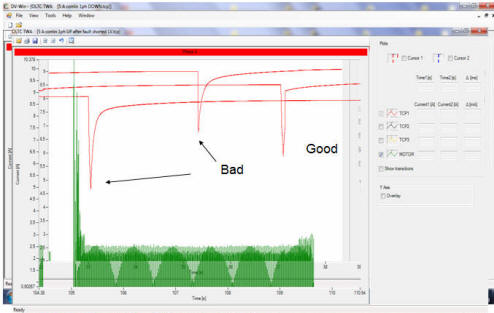
The conclusion: due to the incorrect gear driving the tap changer, the spring was not completely charged to release the energy into diverter operation. Only the subsequent motor operation would add-up the required energy and the diverter switch would operate. It would happen at the very beginning of the subsequent motor operation, and for that reason, a transition for example as indicated from 3 to 4, would occur at the beginning of the 4 to 5 operation. The position of the tap changer was always one position off because of that.